| |
|
|
| |
This guide describes and partially documents the installation of new cam chain tensioners on early Honda V4’s and starts after you have done everything to remove the valve covers on both banks of cylinders and draining the coolant from the front head. If you aren't familliar with doing valve adjustments on these motorcycles, you probably shouldn't be trying this project. |
|
This guide and these photographs should be used in conjunction with a regular shop manual and any other information or help you can find about this subject, some of which is available at the end of this page.
If this is your first time tackling a project like this, it’s worth mentioning… |
|
| |
Some General Wrenching Tips: |
|
Needed Tools and Materials |
|
| |
1) Stay Organized – Misplaced and mismatched screws can be an expensive nightmare on many levels. Spend a couple bucks on organizing bins of various sizes and keep your uninstalled parts together in a logical sequence. 10 seconds now will save you 10 hours later. |
|
- Two wire coat hangers
- Full metric socket Set w/ medium and long extensions
- Various sizes of flat-head screwdrivers
- Safety wire (optional)
- Sharpie pen (optional)
- Plenty of towels and rags to wipe hands and surfaces
- An extra set of hands
|
|
| |
2) Keep records – If a job is complicated it’s easy to get confused with what went where before you took it apart. If you have a small digital camera handy and are unsure about your mechanical skills, snap pictures along the way to record how things looked. |
|
|
| |
3) Don’t get frustrated – If you start feeling frustrated and let yourself continue, you’ll probably cause more problems and damage than you’ll solve or fix. Take a break. |
|
|
| |
|
|
| |
On With the Show - (click all images for larger version) |
|
| |
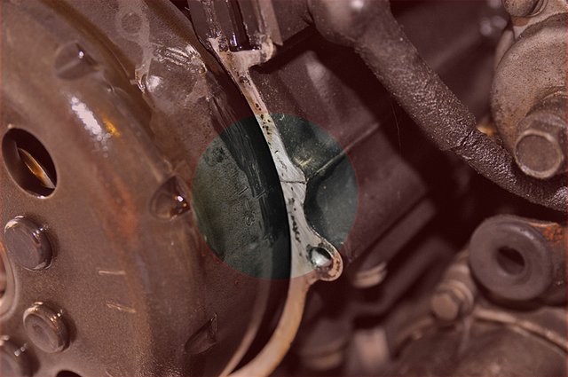
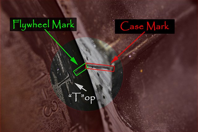
1) Set the bike to Top Dead Center (TDC) 1-3 on the flywheel - Remove the alternator cover and use a 17mm socket wrench to spin the flywheel clockwise to TDC. This is the point at which the cylinder is at the top of it’s compression stroke (check for pressure with your finger over the spark plug hole). The flywheel is marked as 1-3 (rear cylinder banks) and 2-4 (front cylinder banks) with a large “T” next to a line which should get matched against a line on the case. See pictures. (Imgs. 01, 02) |
|
| |
Image 01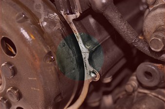
|
|
Image 02 |
|
| |
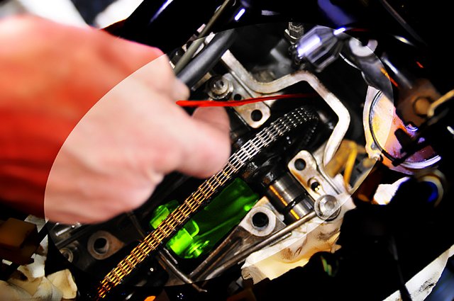
2) Remove cam-chain guide bolts and guide - (Img.03 - bolts in red, guide in green) |
|
Image 03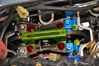 |
|
| |
3) Remove “H” oil pipe bolts – “H” unit can not easily be removed at this point. (Img.04 – bolts circled in Red) |
|
Image 04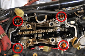 |
|
| |
4) Remove chain tension - Now comes the tricky part which is easier with an extra set of hands around. Before we do this, let’s use Step #4 to only take a look at what we’re playing with before sticking wires and screwdrivers down the engine. Upcoming Stepes 5, 6 and 7 will respectively describe A, B and C below.
In order to take the tension off the chain you’ll need to do three things: |
|
| |
What needs to be done...
|
|
How it's done... |
|
| |
A) Release the tensioner arm slide-stop (Img. 05 – Red) so that you can can… |
|
A) Can be done with a long standard flat head screwdriver. You can see a black “slide-stop” (Img.05 - Red) which, much like a screen door holder, acts like an automatic stopper for the tensioner arm. |
|
| |
B) Lift the end of the tensioner arm, which reduces tension (gives chain slack) on the chain which allows you to… |
|
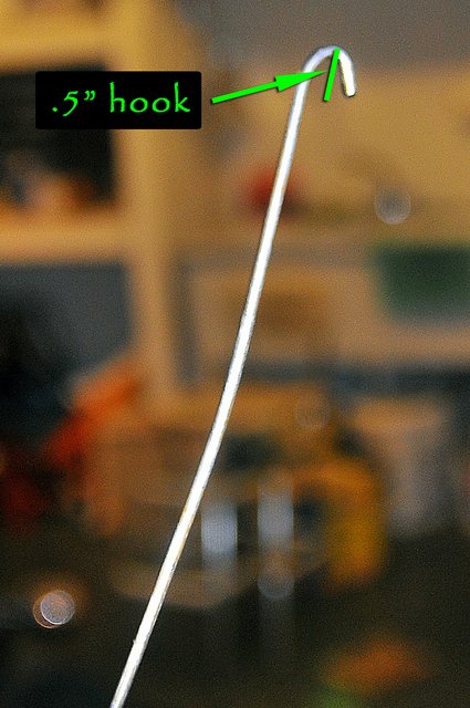
B) Will require some kind of hooked wire which can be fashioned out of an old wire coat hanger. Using a pair of needle-nose pliers to bend a small U-shaped hook of about .3” to .5” deep at one end of the wire. (Img. 06) Since the force required to lift the arm is quite heavy (and your hands will likely be covered in oil), make a “T” shape at the other end of the wire to get a grip. |
|
| |
C) Insert a pin (or “L” shaped coat hanger) into the arm retaining holes (Img. 05 – Green) so the tensioner arm extends away from the tower, removing tension from the cam-chain and allowing you to remove the cam/sprocket assembly. |
|
C) Can also be done with a wire but instead of a “U” shape, bend it into an “L” shape. Make sure the bent extension wire is long enough to go across the width of the tower, about 1.5”. Also be sure the handle is long enough (12 to 24 inches) so that it won’t become yet another thing to drop down into the engine case. |
|
| |
Image 05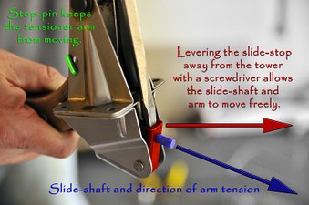 |
|
|
Image 06  |
|
|
| |
- Ready? - |
|
| |
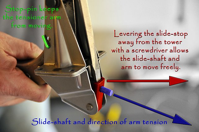
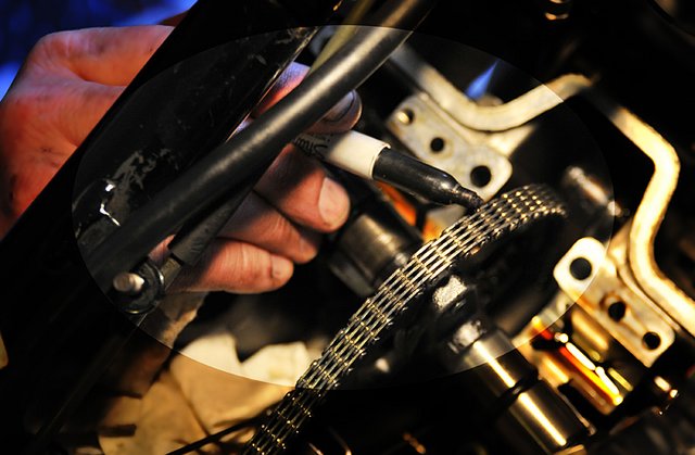
5) Release the tensioner arm slide-stop (Img. 05 – Red) - When this black catch is leveraged AWAY from the tower, it will allow the slide (and therefore arm) to move freely. (Img. 7) |
|
Image 07  |
|
| |
6) Lift the end of the tensioner arm - With the slide and arm free to move, you’ll need to pull up on the end of the arm (using the wire hook) toward the top of the tower. The direction of force and placement of the part makes it conceptually confusing at first but just remember that in this system, the tower spring PULLS the cam-chain slipper toward the tower from the OUTSIDE of the chain inwards. (Img. 08) |
|
Image 08  |
|
| |
7) Insert a pin (or “L” shaped coat hanger) into the arm retaining holes - With the slide and arm free to move, you’ll need to pull up on the end of the arm (using the wire hook) toward the top of the tower. The direction of force and placement of the part makes it conceptually confusing at first but just remember that in this system, the tower spring PULLS the cam-chain slipper toward the tower from the OUTSIDE of the chain inwards. (Img. 09) |
|
Image 09 |
|
| |
Now that there’s some slack on the chain, it’s time to remove the cam and sprocket assembly above the tensioner arm. Since we’re completely removing the cam, we must be careful to install it exactly as it came out or the engine timing will be incorrect. This is a scary step for some but we can do some things to make it a little easier: |
|
| |
|
|
| |
Optionals |
|
| |
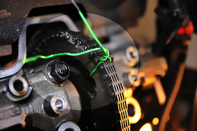
Optional step 1: Use a strong but flexible and shape holding wire (like safety wire) to wire up the un-removed cam (the cam NOT over the tensioner arm) and chain to make sure they don’t accidentally slip orientation. This should be done anytime before removal of the cam which sits over the tensioner arm. (Img. 10 - Green) |
|
Optional step 2: Wipe the sprocket and chain surface dry of oil, then using a Sharpie or better yet, a grease pen, mark how the cam and chain. If the marks survive handling, it will make the chore of reassembling the cam-chain and sprockets much much easier! (Img. 11) |
|
| |
Image 10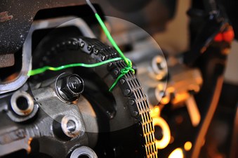 |
|
Image 11 |
|
| |
|
|
| |
8) Remove “H” oil pipe - Now with no tension on the chain you can remove the oil pipe by working it out through its shorter end. It’s worth noting the "long and short" orientation of the pipe and that the oil pipe can be removed or installed any time there’s slack on the chain! |
|
| |
9) Remove the four 10mm cam-chain tension tower bolts at the base of the tower (Img. 12 - Red) - Of all the bolts likely to fall into your engine, these are the ones. Short bolts, covered with oil in a narrow working space are a great combination for disaster. Also, these screws are aluminum and might not be picked up with a magnet.
PLEASE STUFF RAGS OR TOWELS INTO THE ENGINE HEAD TO KEEP SCREWS AND VARIOUS BITS FROM FALLING INTO THE ENGINE!!! |
|
Image 12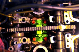 |
|
| |
10) Remove the two 10mm and 12mm screws (Img. 13 – Yellow, two 10mm’s not shown) holding the cam-caps (Img. 13 – Blue) on and remove the cam-caps as well as the the two dowel-pins for each side. (not shown)
Because of the dowel-pins, the cam caps will have to be lifted straight off. Using a large flat-head screwdriver to GENTLY prying them up from the cam lobe will be a good start. DO NOT GOUGE THE SOFT ALUMINUM! Once the caps are off, the dowels need to be removed. If the dowels don’t come out easily, work them out with a set of slip-joint pliers being careful not to pinch them out-of-round. |
|
Image13 |
|
| |
11) Pop the cam and sprocket combo up and towards the tensioner tower - This should happen very easily and with very little force. Be sure to lift both cam sides out at the same time. (Img. 12) |
|
| |
12) Remove the cam and sprocket assembly - With the tower unmounted and the cam popped out, you’ll have mucho slack on the chain and no problem working the chain off the sprocket, enabling easy removal. |
|
| |
13) Separate cam-chain-slipper from tensioner arm - Although the tower is unbolted, it’s not yet free to remove. The cam chain is still running between the arm’s “fingers”(Img. 14 - Green) and the “slipper” (Img. 14 – Red) which guides the chain’s path and puts nice even pressure on the chain over a long area. |
|
Note: Separation of these parts involves removing a pin at the end of the arm which holds the slipper in place. The pin itself (Img. 15 – Yellow) is held in place by a spring clip (Img.15 – Red) and washer (Img. 15 – Blue). --- BE CARFUL NOT TO DROP THE WASHER OR SPRING CLIP INTO THE ENGINE CASE as they are both very small and slippery! Also, the clip is extremely small and can shoot across the room at high speed likely finding it’s way into some dark and hard to access crevasse of your garage. |
|
| |
Image 14 |
|
Image 15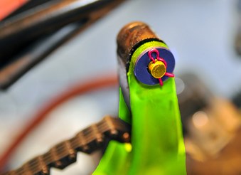 |
|
| |
14) Remove Cam-Chain-tensioner tower - With the slipper removed (Img. 16) you’re now free to fully remove the tower from the engine after clearing the chain from between the fingers.
Congratulations! Now it’s out. All you have to do is put the new one back in! |
|
Image 16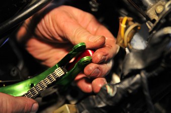 |
|
| |
|
|
| |
Reinstall New Tower |
|
| |
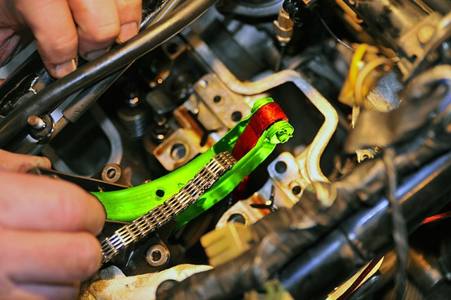
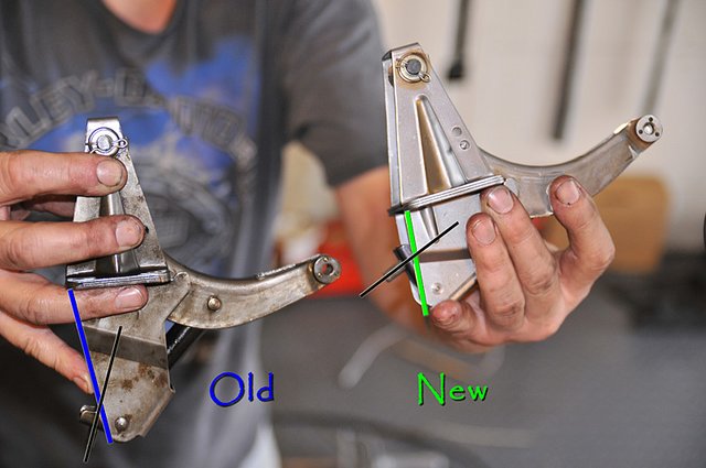
Comparing Original to New: Although fundamentally the same, take a look at the new tower (on the right) which has a shorter lower section. (Img. 17) |
|
Image 17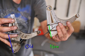 |
|
| |
|
|
| |
Note: Before reinstallation, swap the “L” shaped wire from the old tower to the new one in order to avoid dropping the shorter pin into the engine case when you remove it. This can be difficult since the new tensioner is not mounted to a solid surface and the arm should spring in after the short pin is removed. |
|
Since the new tower isn’t mounted, there’s no easy way to lift the arm to align the holes and reinsert the wire, you’ll have to be creative. During this installation we used good ol’ hand power the first time but found it easier to use a set of pliers to brace the tensioner-slider (which stops the arm from moving) BEFORE removing the new pin. |
|
| |
15) Install slipper into new cam-chain-tensioner arm - Place the cam-chain between the tensioner arm fingers and re-install the slipper pin, washer and spring-clip. DON’T DROP PARTS IN THE ENGINE CASE!!! |
|
| |
16) Install new tensioner-tower - When installing the tower, be sure that the very bottom of the slipper sits in the correct groove next to the timing drive gear at the bottom of the case. If the slipper is not correctly inserted, the tensioner will not work and need reinstalling. |
|
| |
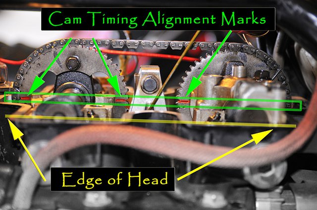
17) Install cam and sprocket assembly – On rare occasions, the crank can turn a little bit from handing the cam-chain. Take a second to check the TDC mark at the flywheel.
When reinstalling and aligning the cam and sprocket assembly, be sure the lines (Img.18 - Red) on BOTH sprockets line up with the edge of the case (Img. 18 - Yellow). If they do not line up, keep adjusting the cam-chain and sprocket tooth setting until they do. This is critical for proper engine timing and NOT an optional detail! (Cyinders 2-4 uses dots instead of dashes) |
|
| |
Image 18 |
|
| |
 |
|
| |
18) Install 4 tower bolts (18ft/lbs) (Img. 12) |
|
| |
19) Install cam caps (10mm - 10ft/lbs; 12mm - 18ft/lbs) – Be sure to re-install the two dowel pins and, once again, be careful not to drop them into the engine. |
|
| |
20) Position “H” oil line unit – Gently lift the still slack cam-chain then slip the “H” oil line unit into place but do not install the screws just yet. |
|
| |
21) Remove wire/pin to release tensioner-arm – This will place tension back on the chain. Check the chain tension between the sprockets, there should be minimal play with no way to take the chain off the teeth. |
|
| |
22) Install four “H” oil unit screws – (10mm - 10ft.lbs torque) (Img. 04) |
|
| |
Optional: If you wired your un-removed sprocket and chain together, unwire it now!!! DO NOT LEAVE THE WIRE IN! |
|
| |
23) Spin crank several times to check chain tension and return to 1-3 TDC (Img. 02) |
|
| |
24) Reinstall Cam-Chain-guide and four 14mm screws (35-38ft.lbs.) - Note: Applying thread-locking compound to these bolts with a is recommended |
|
| |
Congrats! With all this experience under your belt the second set should be easier! Repeat these steps for the front 2-4 cylinder bank. |
|
| |
Notes on 2-4 Cylinder Tensioner Removal and Installation: |
|
| |
1) The chain sags differently on these cylinders due to their orientation. On our install, once we aligned and installed the cam-sprocket-assembly (with cam-caps installed), we noticed slack on the chain even after removing the tensioner arm pin. Should this happen, hold the cam chain guide over the cams and turn the crank a few times being sure it comes back to TDC on the compression stroke. Check the sprocket alignment and chain tension again. If it is still loose then remove the tower and make sure the chain-slipper is properly seated inside the engine case. |
|
2) Instead of lines marking the cam timing (like on the 1-3cams) the 2-4 cams use dots. This makes it all the more important to wire and mark your cam-sprocket and chain orientation. |
|
| |
|
|
| |
After-thoughts and Additional Resources |
|
| |
I hope this has helped provide some clarity on this most unwelcome maintenance chore. Like most knowledge, much of this has come from experience, hard work and mistakes of others, many of whome have also taken the time to record and document this process. Because much of this information has been found and lost through several different corners of the web for years, I’ve provided a link to a zip file containing some of these documents thanks to Craig D’s tremendous record keeping skills. |
|
Although the purpose of this is to centralize the information, should a creator of any of the content wish to NOT have their work included in the zip file, please notify me and it will be removed from the package immediately.
PDF Version of this page is available here:
CC-V4TensionerSwap.pdf
Click the link below for the “V4CamTensionerDocs.zip" reference documents file which includes a PDF version of this page as well.
V4CamTensionerDocs.zip |
|
| |
Finally, If you’re coming upon is document through a method other than a dedicated Honda V4 site, please visit www.sabmag.org and www.V4hondabbs.com for more help from a great community of totally grungy (but lovable) whackos.
Good luck and happy wrenching!
CrazyCarl |
|
| |
|
|
| |
Add your own Questions or Comments below |
|
| |
If you'd like to add any information like where to buy parts, other tips and tricks or V4 Cam-chain trivia to the post above, please feel free to do so here. The more info the better! |
|
| |
|
|
| |
|
|
|
|